
A glass window can survive a high temperature and still crack when cold liquid touches it. The problem is not simply that the glass is hot. It is that one region changes temperature before the rest of the part can follow.
Thermal shock is the rapid development of thermal stress caused by a sudden temperature change. Cracking occurs if the resulting tensile stress is sufficient to extend an existing flaw. A thermal shock does not always cause breakage, but a successful slow heating test does not prove resistance to sudden cooling.
Follow the Temperature Through the Thickness
Imagine a uniformly warm glass plate exposed to cold water on one face. The wetted surface cools and wants to contract while the interior remains warmer. The warmer interior restrains that contraction, leaving the cooled surface in tension.
During rapid surface heating, the basic through-thickness stress tendency reverses: the hotter surface is restrained from expanding by the cooler interior. Actual parts can also bend, and local heating, edges and supports make the stress pattern more complicated. These mechanisms are explained in SCHOTT TIE-32: Thermal Loads on Optical Glass.
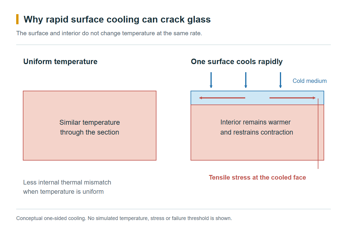
This is why the temperature of the cooling liquid, the area it wets and the speed of contact all matter. A room-temperature spray on a hot observation window is a different event from a controlled cool-down in circulating air.
Three Temperature Specifications That Should Not Be Confused
| Specification | What it describes | What it does not establish |
|---|---|---|
| Operating temperature | Sustained or time-limited thermal exposure under specified conditions | Survival of a sudden quench |
| Thermal shock resistance | Behaviour under a defined rapid temperature-change test | Every thickness, mounting or coolant condition |
| Thermal gradient resistance | Behaviour when regions of a part are at different temperatures | A universal pressure-temperature rating |
For example, SCHOTT’s BOROFLOAT technical information gives different limits for short and long exposure. These are material-use guidelines, not complete viewport approvals. The same technical details also describe temperature differences between a hot panel centre and a cooler edge.
The practical lesson is simple: specifying only a maximum temperature leaves the event that causes thermal shock undefined.
A Thermal Shock Figure Is a Test Result, Not a Universal Limit
SCHOTT publishes a BOROFLOAT 33 example of 175 K for thicknesses up to 3.8 mm in a particular thermal-shock test. Its method uses 200 x 200 mm panels heated in circulating air, then 50 ml of 20-degree-Celsius water applied at the centre. Samples are deliberately abraded before testing, and the stated result is associated with a 5% fracture criterion. See the original test description.
That number is useful because the test conditions are known. It should not be transferred directly to a drilled disc, a thick lens, a pressurised sight glass or another borosilicate grade.
The material family name is not enough either. SCHOTT’s DURAN tubing brochure gives its own thermal-shock guidance for tubing and identifies factors such as wall thickness, geometry and surface condition. Different product forms and test methods can legitimately produce different figures.
Investigate the Event, Not Just the Broken Glass
If an equipment window fails during cleaning or start-up, describe the sequence before choosing a replacement material. Start with where the heat came from, where the cold medium first contacted the glass, and whether the assembly was already carrying another load.
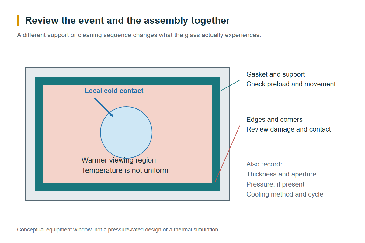
For a useful comparison between replacement designs, record:
- Glass temperature immediately before the event, and the temperature of the incoming medium.
- Contact method: immersion, jet, spray, flowing liquid or air cooling.
- Panel dimensions, thickness, holes and the exposed viewing area.
- Support, gasket, clamp or adhesive arrangement, including any pressure load.
- Existing chips or scratches, and whether failure occurs on the first cycle or after repeated use.
These details make a trial reproducible. Without them, changing from one sample to another may change the test more than the material does.
Reduce the Temperature Difference Where the Part Actually Sees It
The improvement does not always have to be a more expensive glass. A controlled cooling step, a different cleaning sequence or a redesigned thermal barrier may remove the severe local event. If the event cannot be changed, compare candidate materials in the finished geometry and assembly.
Do not run improvised hot-to-cold tests on installed pressure equipment. Qualification should follow a controlled procedure appropriate to the component and its failure consequences.
For lower-expansion material options, see Borosilicate Glass. For the dimensional part of the problem, read the thermal expansion coefficient of glass.