Your Reliable Partner For Custom Special Glass In China
First Engineering Decision

Is the Part a Mechanical Plate or an Optical Window?

An industrial plate is normally controlled by material, outline, holes, edges and strength. An optical window adds surface flatness, parallelism, clear aperture, cosmetic quality, spectral transmission and coating performance.

Separating these paths prevents optical tolerances from being added where they do not improve the equipment.

Specify only the functional zones.A mounting border, gasket land and clear aperture can use different surface and cosmetic requirements on the same part.
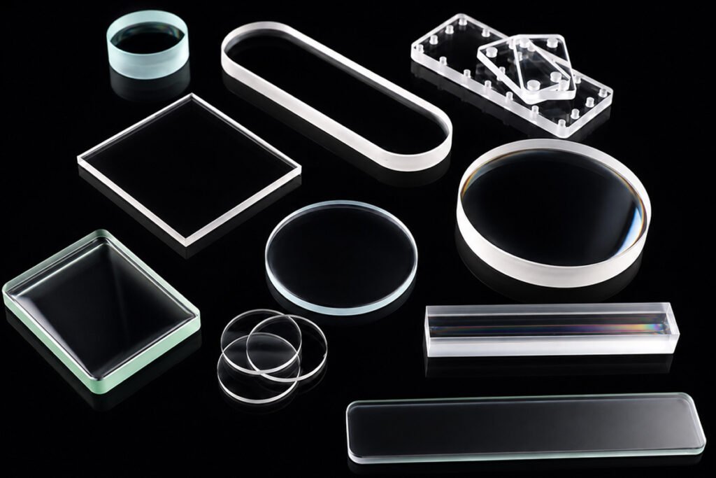
Custom glass plates and precision windows in multiple shapes
Functional area
L / ODWT
Mechanical specification

Control the Geometry That Fits the Assembly

Start with material, finished size, thickness, datum edges, holes, slots and edge condition. Add strengthening, printing or coating only where the service environment requires it.

Primary controls
Outline, thickness, holes, edge finish
Typical inspection
Dimensions, feature position, chips and fit
Do not over-specify
Optical flatness outside the viewing requirement
Reference Manufacturing Envelope

Define Geometry and Optical Quality Separately

The ranges below are useful starting points for RFQ preparation. Final capability depends on material, size, thickness, feature spacing and inspection method.

Materials6 substrate routesSoda-lime through optical glass
Thickness0.5-25 mmReference range by material
GeometryFlat / round / ring / profileMachined to drawing
Mechanical Tolerance+/-0.05-0.10 mmTypical precision range
Optical Flatnesslambda/4 to lambda/10At 632.8 nm, reviewed by size
Surface Quality60-40 to 40-20Better grades reviewed

Reference capability, not a blanket guarantee. Put the tolerance, test wavelength, clear aperture and inspection standard on the drawing.

Dimension & Aperture Drawing

One Drawing Must Separate Mechanical and Optical Zones

Use datums for the mounting geometry and identify the usable clear aperture independently from the physical edge.

L - FINISHED LENGTHW - FINISHED WIDTHCLEAR APERTUREHOLE DIA + POSITIONEDGE DISTANCEEDGE / CHAMFEROPTICAL ZONEDATUM A
AMechanical datumsLocate outline, holes, slots and the mounting interface.
BClear apertureDefines where flatness, surface quality and coating performance apply.
CEdge distanceInsufficient material between a hole and the edge increases local breakage risk.
DProcess orderComplete holes, slots and profiles before thermal tempering.
01

Why Clear Aperture Is Not the Same as Overall Size

The physical plate includes mounting overlap, edge finishing, gaskets and possible coating exclusion zones. The clear aperture is only the area used for viewing or transmitting light. Applying optical flatness and strict cosmetic quality to the hidden border adds polishing and inspection cost without improving system performance.

Material Selection

Match the Substrate to the Window Duty

Temperature, wavelength, chemical exposure, strengthening route and cost determine the starting glass.

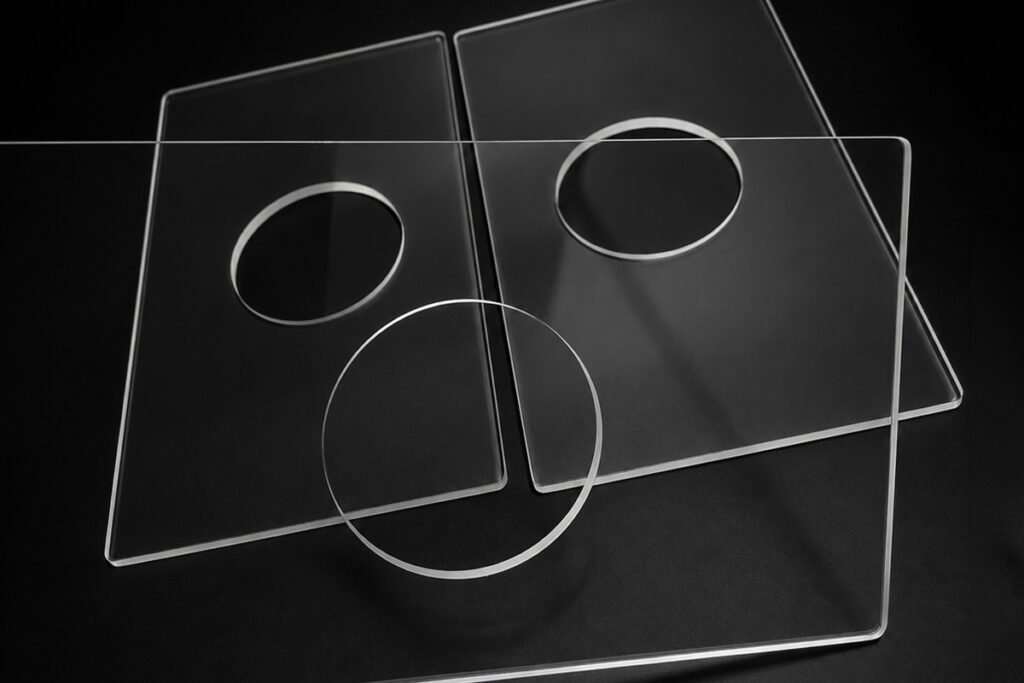
Glass plate with CNC holes and slots
MaterialUse It WhenWatch
Soda-LimeGeneral equipment covers and cost-led industrial platesGreen edge tint and thermal limits
Low-IronColor-neutral viewing and higher visible clarity matterStill define strength and surface need
Borosilicate 3.3Thermal cycling and chemical durability drive selectionAssembly temperature gradient
AluminosilicateThin chemically strengthened covers are requiredGrade and ion-exchange route
Fused Silica / QuartzVery low expansion or grade-specific UV/IR transmission is neededExact grade, OH content and cost
Optical GlassRefractive or spectral behavior is part of the optical designMelt data and coating compatibility
Two Manufacturing Routes

The Finish Level Follows the Function

Industrial plates and precision windows share blank preparation, then diverge where optical surfaces become functional.

Mechanical Route

Assembly-Ready Industrial Plate

  1. Material and blank size
  2. Cut / CNC outer profile
  3. Drill holes and machine slots
  4. Grind edges and clean
  5. Strengthen, print or coat if required
  6. Dimensional and visual inspection
Primary output: fit, protection and direct assembly
Optical Route

Precision Transmitting Window

  1. Optical material and blank
  2. Generate finished geometry
  3. Grind / lap functional faces
  4. Polish clear aperture
  5. Apply spectral coating if required
  6. Interferometric and optical inspection
Primary output: controlled light path and low distortion
CNC machined precision glass window
Available Finishing

Apply Processing Only Where It Creates Function

Available options include through holes, slots, cut-outs, notches, counterbores, recesses, steps, seamed or polished edges, face lapping, optical polishing, thermal or chemical strengthening, ceramic printing and AR, AG, AF or conductive coatings.

Review CNC glass processing
Inspection Plan

Measure the Characteristic That Controls the System

A mechanical cover and a laser window should not share the same inspection plan. The drawing should connect every tight requirement to its inspection method.

Technical glass window inspection and application
GeometryOverall size, thickness, profile, hole and slot positionCaliper / vision measurement / CMM
Edge IntegrityChip limits, chamfer, bevel and crack-free feature edgesVisual / microscope
Optical SurfaceFlatness, parallelism, wedge, scratch-dig and clear apertureInterferometer / optical inspection
CoatingTransmission, reflection, coating side and usable bandSpectrophotometer
DecorationRegistration, opacity, color and protected print zoneVision / color measurement
Final ConditionCleanliness, orientation, part identity and protective packingFinal release record
Application Matrix

Start From the Equipment Interface

The same flat glass form becomes a different product when its mounting, spectrum, temperature or cleanliness requirement changes.

ApplicationStarting MaterialCritical Specification
Industrial enclosure windowSoda-lime / borosilicateMounting geometry, edges, impact and cleaning
Furnace viewing windowBorosilicate / fused silicaTemperature gradient, atmosphere and aperture
Laser protective windowSelected fused silicaGrade, wavefront, surface quality and coating band
Machine vision windowOptical glass / fused silicaParallelism, distortion, clear aperture and AR
Instrument or display coverLow-iron / aluminosilicateColor, print registration, strength and surface treatment
Laboratory technical plateBorosilicate 3.3Chemical exposure, holes, flatness and fit
Procurement FAQ

Glass Plate & Window Questions

Answers for drawing, optical surface and process planning.

What information distinguishes an industrial plate from an optical window?

An industrial plate is mainly defined by material and geometry. An optical window also needs clear aperture, wavelength range, surface quality, flatness, parallelism or wedge and any coating specification.

What thickness range can be reviewed?

A practical reference range is about 0.5-25 mm. Availability depends on material, finished size, feature geometry and surface finish.

Can holes, slots and recesses be included?

Yes. Through holes, slots, cut-outs, notches, counterbores and selected recesses can be produced in compatible geometries before strengthening.

Can a window be polished only inside the clear aperture?

Yes. Functional zones can be specified separately so optical finishing and strict cosmetic inspection apply where the system uses the light path.

What do 60-40 and 40-20 describe?

They are commonly used scratch-dig surface-quality grades. State the inspection standard and the area where the requirement applies.

Can AR coating, printing and strengthening be combined?

They can be combined on suitable materials, but the order, coating side, print zone and strengthening method must be reviewed together.

Can tempered glass be drilled afterward?

No. Conventional holes, slots, cut-outs and edge profiles must be completed before thermal tempering.

What should be sent for quotation?

Send the drawing, material or operating environment, dimensions, datums, tolerances, clear aperture, surface quality, wavelength or coating need, quantity and inspection requirement.

RFQ Preparation

Send the Finished-Part Drawing

Mark mechanical datums and optical zones separately. This lets engineering choose the shortest process route that still meets the assembly.

Include these details:
  • Material or operating environment
  • Finished size and thickness
  • Datums, holes, slots and edge profile
  • Clear aperture and optical surface specification
  • Strengthening, printing and coating sides
  • Quantity and inspection documents
Request a Quote
Contact Our Glass Engineers

We're Here To Help

Tell us whether the part is a mechanical plate, optical window or a combination of both, then attach the drawing and required inspection level.

Saving your time and cost is our common pursuit.

Tell us the material, size, thickness, tolerance, quantity, application, and any holes, slots, edges, coating, printing, or polishing requirements. We can manufacture custom glass components from your drawing, CAD file, sketch, or sample.

Address
Yunpu Industrial Zone, Nangang, Huangpu District, Guangzhou
Wechat
+86 19860070065