
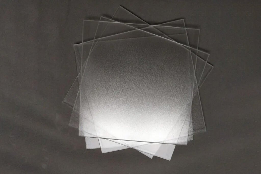
Display Interface
Visible-Band Display AR Glass
Broad visible design for HMI, medical displays and control panels.
Anti-reflective coatings use optical interference to reduce reflection over a selected wavelength range. A single headline number is incomplete unless it states whether the value is per surface or total, average or maximum, and measured at which wavelength and angle.
Substrate absorption, coating on one or both sides, residual hue, polarization and angle of incidence affect the final appearance. Touch surfaces also need a compatible easy-clean layer and a durability plan.
| Design band | Visible 400-700 nm or an application-specific optical band |
|---|---|
| Reflection target | Average/maximum and per-surface/total definition required |
| Transmission | Measured with substrate, thickness and coating-side count stated |
| Coating side | One side or two sides, identified relative to the assembly |
| Angle of incidence | Normal incidence or a specified angular range |
| Durability | Abrasion, adhesion, humidity, heat and cleaner tests by application |
Reference ranges are used for discussion only. The quotation identifies the controlled values and inspection method.
The chart shows the shape of a typical broad-band comparison. It is not measured SpecialGlass production data.
Specify whether the limit is average, maximum, per surface or total glass reflection, and state the wavelength and angle.
The correct route depends on spectrum, surface count, exposure and the assembly behind the glass.
Broad visible design for HMI, medical displays and control panels.
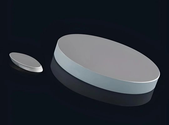
Reduces total front and rear surface reflection where both faces meet air.
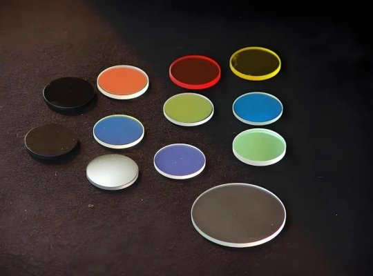
Low-reflection stack with an outer easy-clean surface and retained-durability target.
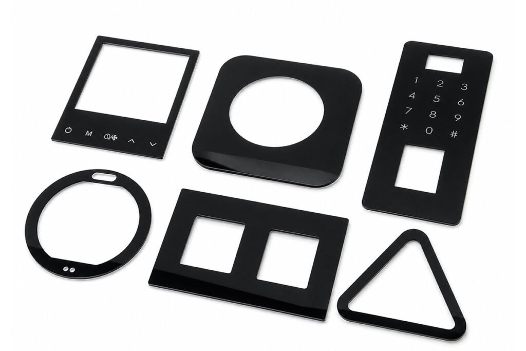
Coating centered on an agreed wavelength range, angle and substrate.
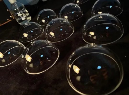
Process sequence coordinated with thermal or chemical strengthening limits.
An AR stack is designed so reflections from multiple interfaces cancel over a target band. When light arrives at a larger angle, the optical path through each layer changes. The reflectance minimum can shift in wavelength and the residual color can change, with polarization becoming relevant at wider angles. Curved display covers therefore need spectral and visual evaluation across the installed viewing geometry rather than only a normal-incidence coupon result.
AR release combines instrument data with controlled visual inspection because a low average reflection can still hide color or uniformity problems.
Lock substrate, coating side, optical or electrical target, test method and downstream process.
Complete cutting, CNC, edge work, cleaning and any compatible strengthening before the controlled coating step.
Apply the selected etch or coating route with orientation, masking and handling controls.
Measure the page-specific optical, surface or electrical characteristics and record uniformity.
Inspect controlled zones and protect the functional surface against contact and contamination.
Inspection conditions and acceptance limits are linked to the approved drawing and coating specification.
Clarify how the number is measured before asking suppliers to match it.
It must state the wavelength range, angle, number of coated surfaces and whether the limit is average, maximum or total glass reflection.
No. AR reduces reflected energy through interference. AG spreads reflected light through surface texture.
Yes for compatible systems. The outer AF layer, optical shift and retained performance after abrasion need validation.
Residual reflection depends on coating design, thickness, substrate and viewing angle. Define the acceptable color by spectrum and physical sample.
Selected curved parts can be reviewed, but angle-dependent color, coating uniformity, fixture shadowing and handling must be considered.
Two air/glass interfaces may need two-side AR. If one face is bonded with index-matched adhesive, the stack can require a different treatment.
Include: Wavelength band and angle | Average/maximum reflectance definition | Transmission and residual-color target | One-side or two-side coating | Substrate, thickness and strengthening | AF/AG or bonding requirements | Durability test and sample quantity.
State how the AR result will be measured and how the coated glass sits in the optical stack. The review identifies the proposed substrate, coating route, measurement method, sample plan and open technical points.
Tell us the material, size, thickness, tolerance, quantity, application, and any holes, slots, edges, coating, printing, or polishing requirements. We can manufacture custom glass components from your drawing, CAD file, sketch, or sample.