
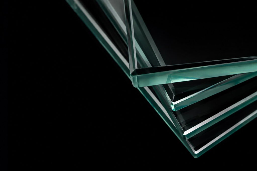
Single Axis
Cylindrical Curved Glass
Constant-radius geometry with chord, sag and tangent dimensions controlled from one bend axis.
Terms such as 2.5D, 3D, curved and bent are used loosely. For manufacturing, the drawing must identify bend axes, radii, arc direction, chord, sag, tangent transitions, edge profile, surface orientation and the coordinate system used to inspect the final shape.
Material viscosity, thickness, panel size and forming method affect feasible radius, profile repeatability, surface marks and optical distortion. We therefore review the complete geometry and quality map before confirming tooling or tolerances.
| Form families | Cylindrical bends, edge bends, multi-radius profiles and selected compound forms |
|---|---|
| Input data | 2D controlled drawing plus 3D CAD surface for formed geometry |
| Key dimensions | Inside/outside radius, chord, arc length, sag, angle, tangent length and edge coordinates |
| Substrates | Soda-lime and selected strengthenable or technical glass after forming review |
| Post-process | CNC/edge work, strengthening, printing and coatings arranged in a compatible sequence |
| Approval | Tooling sample, coordinate report and physical cosmetic/optical sample |
Values and acceptance methods are fixed during drawing, material and sample review.
Rotate between reference forms to see which geometry terms must appear in the RFQ.
One principal bend axis. Specify inside or outside radius, arc direction, chord, sag and tangent lengths.
Geometry visualization only. It is not a dimensional or optical simulation.
A radius alone does not fully define a finite curved panel. The same nominal radius can describe different parts when the chord, arc length, included angle or tangent sections differ. Conflicting dimensions force interpretation at tooling stage and make inspection ambiguous. The controlled drawing should identify the governing dimensions, reference surface and coordinate system, with a 3D model for compound forms.
Each type represents a different engineering and purchasing route. Final dimensions, materials and validation requirements remain drawing-specific.
Constant-radius geometry with chord, sag and tangent dimensions controlled from one bend axis.
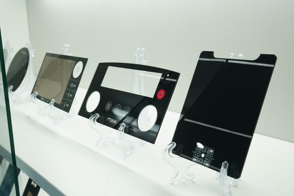
Localized curved transitions for controls, displays and decorative interfaces.
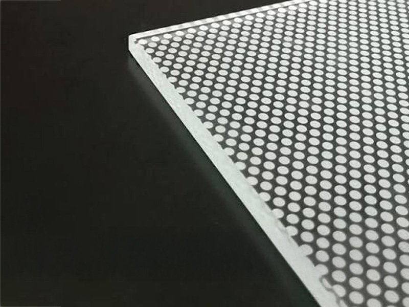
Multi-axis forms requiring 3D inspection, tooling review and optical mapping.
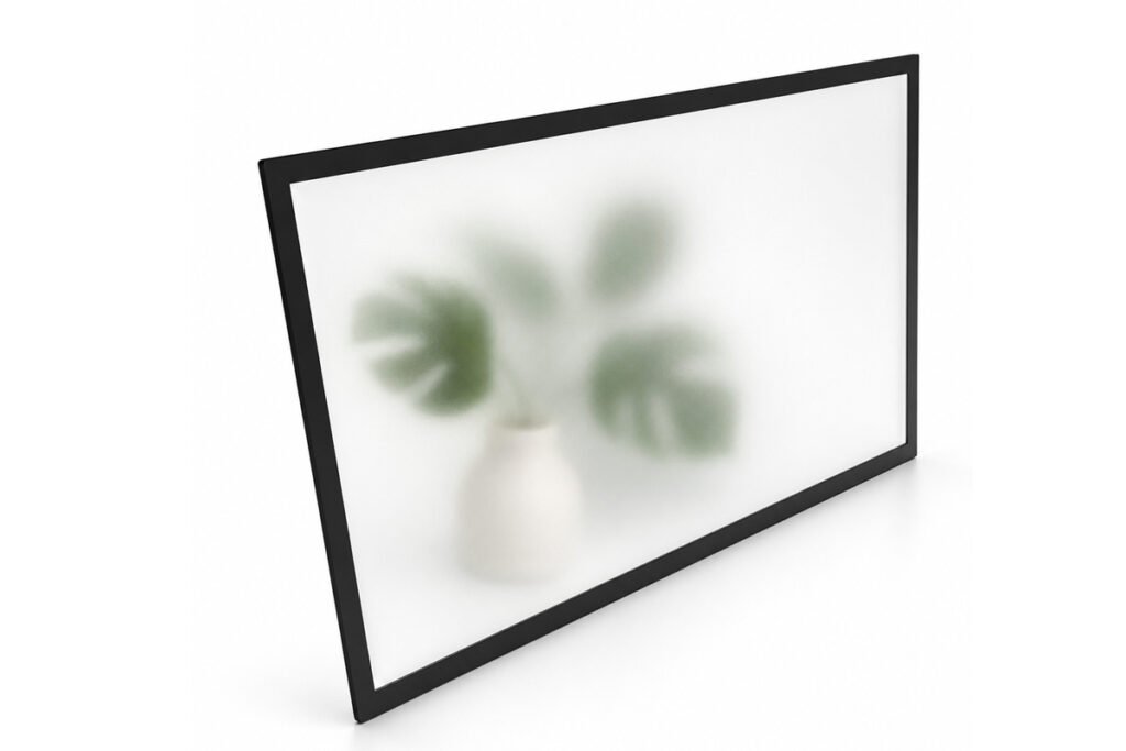
Formed glass coordinated with display viewing geometry, coatings and bonding.
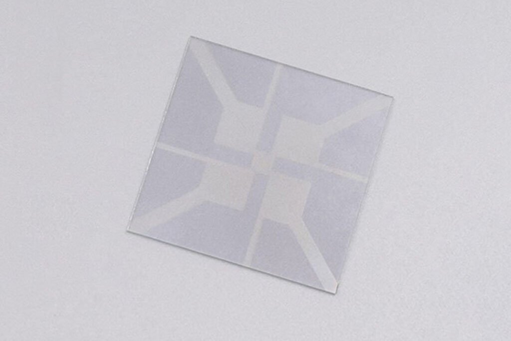
Curved printed panels for control surfaces and industrial product enclosures.
A formed part can meet edge dimensions while still showing local profile error, warp or optical distortion. Inspection must match the functional surface.
Lock the drawing revision, substrate, visual zones, test plan and sample quantities.
Machine the outline, holes, slots and edge profiles with the correct process allowance.
Remove particles and residues before printing, strengthening, coating or bonding.
Apply the approved printing, strengthening, surface treatment or forming sequence.
Inspect controlled characteristics and protect cosmetic surfaces for shipment.
Inspection frequency, method and acceptance limits follow the approved control plan.
Curved glass pricing and feasibility are driven by geometry, quality map and production volume.
There is no single value. It depends on glass composition, thickness, panel size, bend angle, forming process, tooling and optical/profile tolerances.
Not necessarily. 2.5D often describes polished or locally curved edges, while 3D formed glass changes the main surface geometry. Define the actual profile instead of relying on the label.
Possible routes depend on whether features are machined before or after forming and strengthening. Their location, size and edge distance require specific review.
Selected coating systems can be applied, but coating uniformity, color shift and durability across the curvature must be validated.
Options include fixtures, templates, coordinate measurement and surface scanning. The method, datum alignment and sampling map should be agreed before tooling approval.
It verifies springback/profile, mold marks, optical distortion, edge coordinates and downstream printing/coating compatibility before production release.
Include: STEP/IGES or equivalent 3D surface | Controlled 2D drawing and datum system | Material and thickness | Inside/outside radius convention | Profile-deviation and optical criteria | Printing/coating surface orientation | Prototype and production quantity.
Curved-glass feasibility and tooling cannot be confirmed from a photograph or outside dimensions alone. Our review identifies the proposed substrate, process sequence, open technical points and the characteristics that need sample approval.
Tell us the material, size, thickness, tolerance, quantity, application, and any holes, slots, edges, coating, printing, or polishing requirements. We can manufacture custom glass components from your drawing, CAD file, sketch, or sample.