
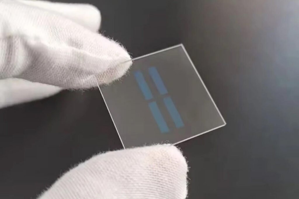
Higher Conductivity
Low-Resistance TCO Glass
Typical 5-10 ohm/square grades reduce electrode resistance where current collection is the priority.
TCO solar glass combines a transparent glass substrate with an electrically conductive oxide surface. FTO, or fluorine-doped tin oxide, is commonly selected where the conductive coating must tolerate elevated-temperature photovoltaic processing.
The useful configuration balances sheet resistance, transmission, haze and surface morphology. The best result is selected around the absorber architecture rather than by choosing the lowest resistance alone.
| Conductive layer | FTO / SnO2 transparent conductive oxide |
|---|---|
| Glass substrate | Clear or low-iron soda-lime glass |
| Common thicknesses | 3.2 / 4.0 mm; other substrates by review |
| Sheet resistance | Typical 5-15 Ω/□ |
| Visible / PV transmission | Typical above 80%, configuration dependent |
| Haze | Approx. 0.5-15% from low- to high-haze grades |
| Inspection | Sheet resistance, transmission, haze, surface and dimensions |
Unless stated otherwise, numerical values are typical industry references. Final capability and acceptance limits are confirmed against the ordered construction, test method and approved specification.
Select a real performance grade according to the photovoltaic deposition and light-management requirements.
Typical 5-10 ohm/square grades reduce electrode resistance where current collection is the priority.
Approx. 0.5-2% haze for applications favoring direct transmission and a smoother deposition surface.
Textured conductive surfaces scatter light and can increase the optical path in selected thin-film absorbers.
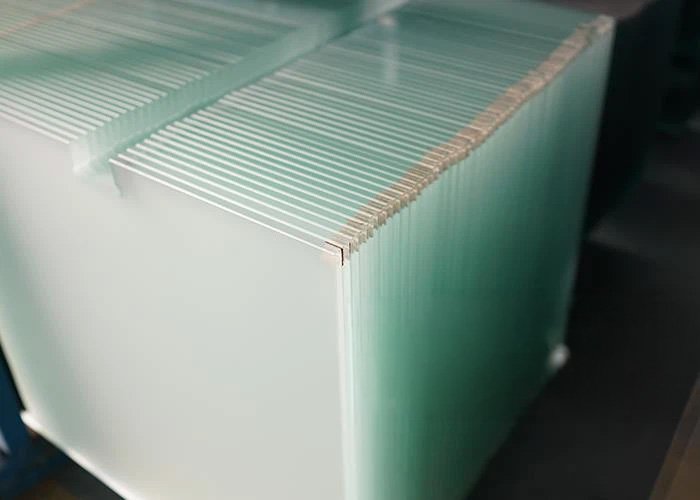
A lower-iron substrate reduces absorption before light reaches the conductive layer and photovoltaic stack.
Select a layer to see its engineering role. The conductive face must remain identified and protected through processing and packing.
Transmission must be measured over the wavelength range relevant to the intended photovoltaic absorber.
Specify spectral range, incidence condition and test method.The substrate supplies dimensional stability and optical transmission. Lower iron reduces absorption in the glass itself.
Specify thickness, size, edge and substrate composition.The oxide surface transmits light while carrying electrical current. Resistance, uniformity, haze and morphology all matter.
Protect and identify the conductive side during every downstream operation.The preferred haze and surface morphology depend on whether the absorber is a-Si, tandem silicon, CdTe, perovskite or another architecture.
Share the deposition route and maximum process temperature.These values must be reviewed together. A lower resistance grade may use a different coating thickness or morphology, while higher haze may help one absorber but add no benefit to another.
| Configuration | Typical Range | Primary Use |
|---|---|---|
| Low resistance | 5-10 Ω/□; low-medium haze | Higher lateral conductivity |
| Balanced TCO | 7-15 Ω/□; medium haze | General thin-film structures |
| Low haze | Approx. 0.5-2% haze | CdTe or smoother deposition route |
| High haze | Approx. 5-15% haze | Thin-film silicon light trapping |
| Low-iron TCO | Application-specific resistance/haze | Reduce substrate absorption |
Textured TCO can lengthen the optical path in a thin absorber, but the benefit depends on cell architecture and interface quality. Highly absorbing materials may need less scattering, while a rougher surface can also affect subsequent film deposition. Haze must therefore be selected with the photovoltaic process.
The coating route is controlled upstream; finished substrates then require careful handling, dimensional processing and dual electrical/optical inspection.
Control glass composition, cleanliness and coating face.
Form the transparent conductive oxide under controlled conditions.
Check resistance, transmission, haze and uniformity.
Cut to size and process compatible edges while protecting the coating.
Mark the conductive side and prevent scratches or contamination.
Inspection limits and reporting level follow the drawing, purchase specification and approved sample.
TCO glass is the transparent front electrode, not simply protective cover glass.
Controlled-haze FTO substrates can add light scattering within thin silicon absorber layers.
High-haze surface options support light trapping across stacked amorphous and microcrystalline absorbers.
High-transmission, lower-haze conductive surfaces are commonly considered for strongly absorbing CdTe structures.
Cut-to-size FTO glass supplies the transparent electrode for coated laboratory, pilot and specialty photovoltaic devices.
Electrical and optical requirements should be written into the same purchase specification.
It is glass coated with a transparent conductive oxide, allowing light to pass while supplying an electrically conductive electrode surface.
FTO, or fluorine-doped tin oxide, is commonly used because it combines transparency, conductivity and thermal stability.
Typical photovoltaic configurations are approximately 5-15 ohm/square. The required grade depends on cell architecture, panel size and acceptable optical trade-offs.
Common solar TCO references exceed 80%, but the controlled value depends on substrate, coating resistance, haze, wavelength range and test method.
Low-haze grades may be around 0.5-2%, while textured grades may reach approximately 10-15%.
Neither is universal. Thin-film silicon may benefit from scattering, while CdTe and smoother film stacks may use lower haze.
Yes. Rectangular substrates can be cut and supplied with compatible edge processing and clear conductive-side identification.
Key checks include sheet resistance, resistance uniformity, spectral transmission, haze, coating defects, dimensions, edges and surface cleanliness.
Include: Photovoltaic technology and process temperature | Required sheet resistance and uniformity | Transmission range and test method | Haze or surface morphology target | Substrate type, thickness and dimensions | Edge finish, coating-side marking and packing.
For TCO glass, identify the cell architecture and downstream process before fixing a resistance or haze target.
Tell us the material, size, thickness, tolerance, quantity, application, and any holes, slots, edges, coating, printing, or polishing requirements. We can manufacture custom glass components from your drawing, CAD file, sketch, or sample.