
“Put the hole 12 mm from the edge” leaves a critical question unanswered: is 12 mm measured to the hole center or to the nearest wall of the hole? Those two drawings can produce very different glass parts.
Before choosing a minimum distance, define the geometry. For a circular hole beside a straight edge, the remaining ligament is the center-to-edge distance minus half the hole diameter. This is a dimensional relationship, not a formula for approving strength.
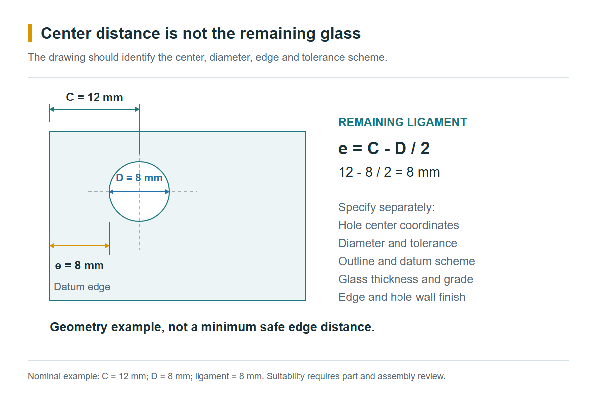
Put Centers on Datums, Then Check the Ligament
Specify the hole center from identified reference edges or datums. State the diameter and its tolerance separately. This gives the manufacturer and inspector the same coordinate system and avoids a chain of dimensions that becomes ambiguous when several holes are added.
In the illustrated example, an 8 mm hole centered 12 mm from a straight edge leaves an 8 mm ligament. With a 10 mm hole at the same center, the nominal ligament falls to 7 mm. The center has not moved, but the remaining glass has changed.
For a conservative dimensional check, use the nearest permitted center position and the largest permitted hole diameter. Include the outline tolerance if the physical edge can move relative to the chosen datum. The drawing should make those relationships explicit rather than hiding them in a note saying “holes to suit.”
Why a Small Remaining Distance Needs Review
Holes and cut-outs interrupt the load path. Features close to an edge, corner or another opening deserve particular review, especially where mounting hardware applies force. Surface and machining damage also influence how a brittle part responds to tension; an acceptable hole diameter alone does not establish adequate strength.
SCHOTT’s TIE-33 emphasizes surface flaws and stress concentration in glass design, and recommends avoiding sharp corners and edges where possible. Its guidance concerns defined optical-glass conditions. A spacing recommendation from that document must not be lifted into a universal rule for every thin cover or tempered equipment panel. SCHOTT TIE-33
That is why a manufacturer should review the actual material, thickness, hole form, edge quality, strengthening and assembly. “We made this distance before” is useful experience, but it is not proof that a different part under a different load is suitable.
Complete Holes Before Thermal Tempering
Design changes need to reach fabrication before the glass is strengthened. Pilkington’s Planar specification explicitly places holes and edgework before toughening. Once a panel is thermally tempered, drilling a new fixing hole is not a normal finishing operation; a revised panel is required. Pilkington Planar specification
Confirm the final drawing revision before production. A small change to a mounting bracket can alter the hole pattern, the required clearance or the ligament, even if the overall panel dimensions remain unchanged.
A Hole That Fits Can Still Be Loaded Incorrectly
Showing the screw diameter is not enough to describe the interface. Add the intended bush, sleeve, washer or gasket arrangement, the contact faces and the assembly conditions. Ask which surfaces are intended to carry load and whether the hardware can introduce direct hard contact or uneven clamping.
If a slot allows positional adjustment, show its width, length, end radii and orientation. Specify the hole-wall and edge finish where they are functionally important. Do not use a tight positional tolerance as a substitute for an assembly clearance requirement: one controls manufacturing location, while the other concerns how parts fit together.
For quotation, a dimensioned drawing plus a short installation section is more useful than a photograph of the finished machine. Together they let the fabricator review the glass feature and the interface that will load it.
See Glass Plates & Windows for processed flat components. For the order of operations, read the related article on chemical strengthening and thermal tempering.