
Use CNC When Feature Relationships Control the Fit
A single hole does not make a part complex. CNC becomes valuable when the outside profile, hole pattern, connector opening, recess and alignment notch must remain related to the same datum system.
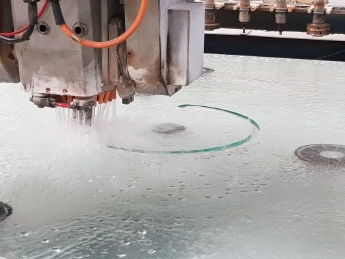
Diamond tooling removes brittle glass progressively. Remaining wall, internal radius, feature depth and edge distance therefore matter as much as the nominal dimensions.
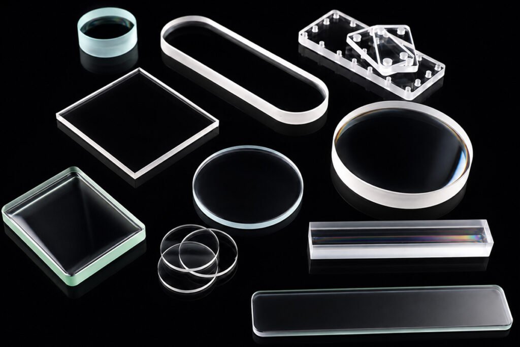
Reference ranges from common industry capability. Final tolerance depends on part size, material, wall, depth, surface finish and inspection datum.
Check the Drawing Before Tightening Tolerances
Select the main conditions. The output identifies a sensible process and inspection starting point, not an automatic quotation.
Blank + diamond drilling + edge grinding
Use one datum setup for the outside profile and hole position, then inspect dimensions and edge condition before any secondary process.
- Primary risk
- Hole-to-edge distance and local chipping
- Inspection start
- Overall geometry, hole diameter and feature position
- Engineering review
- Confirm thickness, wall and whether the part will be tempered
Build the Part Around Datums, Walls and Transition Radii
The drawing should describe how features relate, not only list their individual sizes.
Why Sharp Internal Corners Become a Manufacturing Risk
Diamond tools have a physical radius, and brittle glass concentrates stress at sharp transitions. A practical inside radius improves tool access, reduces localized chipping and leaves a stronger remaining section. Show the minimum acceptable radius instead of drawing an ideal zero-radius corner.
Select the Operation by Feature
CNC is not one process. Surface grinding, cylindrical grinding, drilling and milling control different characteristics.
| Operation | Controls | Reference Range |
|---|---|---|
| Surface Grinding | Local thickness, reference faces and reduced zones | +/-0.05 mm |
| Cylindrical Grinding | Round OD on discs, rings and circular parts | +/-0.01 mm on suitable geometry |
| Edge Grinding | Outside profile and finished edge relationship | +/-0.01 mm on suitable geometry |
| Diamond Drilling | Through holes and repeated hole patterns | +/-0.05 mm; approx. 2 mm standard minimum |
| CNC Milling | Slots, cut-outs, notches, pockets and steps | +/-0.05 mm reference |
| Lapping / Polishing | Flatness, parallelism and transparent functional faces | Specified by surface and aperture |
The Relationship Between Features Is Often the Tightest Requirement
A panel may contain an outside profile, mounting holes, display opening, connector slot, recessed area and alignment notch. Machining these from one controlled coordinate reference reduces relocation error between operations.
- Choose functional datum edges or a center axis
- Dimension feature position from those datums
- Avoid long chains of dependent dimensions
- State whether position or individual size is critical
- Connect inspection points to the same reference system
Tighten Only the Dimensions That Affect Assembly
Several independent choices can move a part from a standard route into slower grinding, lapping or special inspection.
Why Glass Is Machined Before Thermal Tempering
Thermal tempering creates a compressive surface layer balanced by internal tensile stress. Conventional drilling or milling after tempering disturbs that stress field and can release the entire part. Complete the outline, holes, slots and edge work first, then clean and temper the compatible geometry.
From CAD to an Assembly-Ready Component
The process is selected from the finished drawing, material behavior and functional surface.
- 01DFM & Material Review
Check walls, radii, feature depth, tolerance and secondary processes.
- 02Blank Preparation
Cut stock with allowance for grinding and datum creation.
- 03Datum Setup
Establish the reference used by profiles and related features.
- 04Diamond Machining
Drill, mill, grind and generate the finished geometry.
- 05Surface / Secondary Work
Lap, polish, strengthen, print or coat where compatible.
- 06Inspection & Packing
Release against drawing, functional zones and agreed records.
A Measurement Plan for Multi-Feature Parts
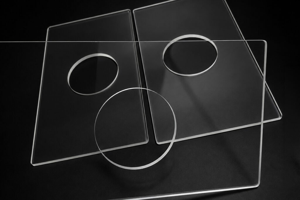
Machining Routes by Equipment Function
Use the application to identify the material, feature set and inspection priority.
| Equipment | Starting Material | Machined Features |
|---|---|---|
| Industrial sight equipment | Borosilicate | Outer profile, mounting geometry, polished aperture |
| Heating and cooking equipment | Glass-ceramic | Control cut-outs, slots, edge profiles and print registration |
| Laser / optical equipment | Selected fused silica | Precision outline, mounting features and optical finishing |
| Display and electronic device | Low-iron / aluminosilicate | Camera opening, sensor hole, slot and rounded profile |
| Industrial enclosure | Soda-lime / borosilicate | Mounting holes, cut-outs and finished edges |
| Laboratory / analytical | Borosilicate / fused silica | Holes, channels, recesses and controlled reference faces |
CNC Machined Glass Questions
Answers for geometry, process order and inspection planning.
When does a glass part need CNC machining?
Use CNC when the part needs controlled profiles, holes, slots, recesses, steps or several features related to one datum system.
What glass materials can be machined?
Soda-lime, low-iron, borosilicate, glass-ceramic and quartz or fused silica can be reviewed. Tooling and process conditions change with material and geometry.
What tolerances are available?
Reference ranges are about +/-0.05 mm for common surface grinding, drilling and milled features, with +/-0.01 mm possible on suitable cylindrical or edge-ground geometry. Final values require drawing review.
What is the standard minimum drilled hole?
Diamond core drilling commonly starts around 2 mm. Smaller holes may need laser or another micromachining route.
Can steps, recesses and custom cut-outs be produced?
Yes. State width, depth, remaining floor or wall, inside radius and surface requirement so feasibility can be checked.
Can several features be held from one datum?
Yes. Single-setup machining is preferred where hole, slot and profile positions must stay related to the same coordinate system.
Can the part be polished and coated?
Yes. Selected faces and edges can be lapped or polished, followed by compatible strengthening, printing or coating.
Can the glass be tempered after CNC machining?
Compatible parts can be tempered after all conventional machining, drilling and edge finishing are complete.
Do you accept prototypes and customer-supplied blanks?
Prototype quantities and customer-supplied blanks can be reviewed with material identity, available machining allowance and acceptance criteria.
What should be sent for quotation?
Send a PDF plus DXF or STEP where available, material, quantity, datums, tolerances, surface zones, secondary processes and inspection requirements.
Send CAD With Functional Datums Marked
Tell us which dimensions locate, seal, align or transmit. Engineering can then protect the important relationships and relax nonfunctional ones.
- PDF drawing plus DXF / STEP if available
- Material or operating environment
- Datums and critical feature relationships
- Tolerance, radius and remaining-wall limits
- Ground, polished or optical surfaces
- Quantity and inspection documents
We're Here To Help
Send the drawing, material, quantity, critical dimensions and finished surface requirements for a manufacturing-route review.
Saving your time and cost is our common pursuit.
Tell us the material, size, thickness, tolerance, quantity, application, and any holes, slots, edges, coating, printing, or polishing requirements. We can manufacture custom glass components from your drawing, CAD file, sketch, or sample.
- Address
- Yunpu Industrial Zone, Nangang, Huangpu District, Guangzhou
- Call Us
- +86 19860070065
- Email Address
- info@specialglass.net
- +86 19860070065
- +86 19860070065